Sometimes malfunctions occur in means of transport that are not always due to internal breakages of mechanical components, but often they arise from incorrectly functioning electronic components including speed sensors.
In this short article we will explain in detail how the functionality verification of the speed sensors mounted on all TE transmissions through the APC200 takes place.
SPEED SENSORS OF TE TRANSMISSIONS: WHICH ONE ARE THEY?
There are 4 speed sensors installed on TE transmissions:
- 0.22 sensor (drum speed in our case),
- Sensor 1.24,
- 2.26 sensor,
- Sensor 3.41.
CHECK SPEED SENSORS – NECESSARY TOOLS FOR ANALYSIS OF THE FAULT
To check the speed sensors we use:
- The APC200 control unit
- The vehicle (or an electric motor to simulate the rotation of the gears.)
SPEED SENSOR TEST TRANSMISSIONS TE: THE PROCEDURE
To check the functionality of the speed sensors, first of all we need to enter the diagnostics of the APC200 control unit, then while turning on the vehicle’s ignition I hold down the S button until 4 zeros appear on the reader.
Once you have entered the diagnostics, I repeatedly press the M Button until the word SPD which represents the 4 speed sensors is displayed, in order we will find:
- Digital input,
- Analogic Input,
- SPD or Spid.
At this point, to analyze the operation of each sensor it is necessary to turn on the vehicle and press the S button, the APC200 control unit will show the data it detects for each sensor on the dial.
SPEED SENSORS: TYPES OF MALFUNCTIONING.
The faults that can be attributed to a speed sensor are essentially two: malfunction or a wiring problem (lack of contact).
How to recognize the problem detected?
In case of sensor malfunction, on the APC200 control unit, entering the SPD diagnostics we will see 4 zeros, but analyzing sensor by sensor we will notice that a speed sensor is not read and therefore does not return data to the display.
On the other hand, in case of lack of contact (disconnection of a connector or sheared cable) in the SPD diagnostic we will no longer find the 4 zeros, but a dash will be signaled by the APC200 control unit in correspondence with the contactless sensor. Then, by analyzing the sensor in question, the word OPEN will appear.
CHECKING THE FUNCTIONALITY OF THE SPEED SENSORS OF THE TRANSMISSIONS WITH THE APC200: THE VIDEO
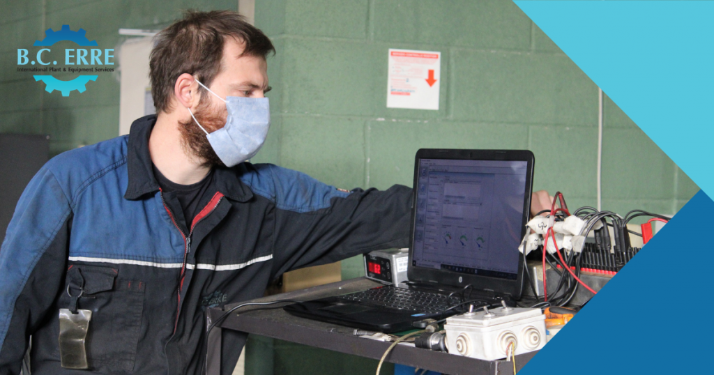
Watch the video and see the explanation of the technician B.C. Erre while proceeding to check the functionality of the speed sensors mounted on the TE transmissions through the APC200 control unit.


